When connecting more than 5x SSLB1 batteries in parallel it often results in interference along the comms cables which stops all interlink communications between the batteries.
In order to overcome this a change must be made to the parallel comms cable between battery 5 and battery 6.
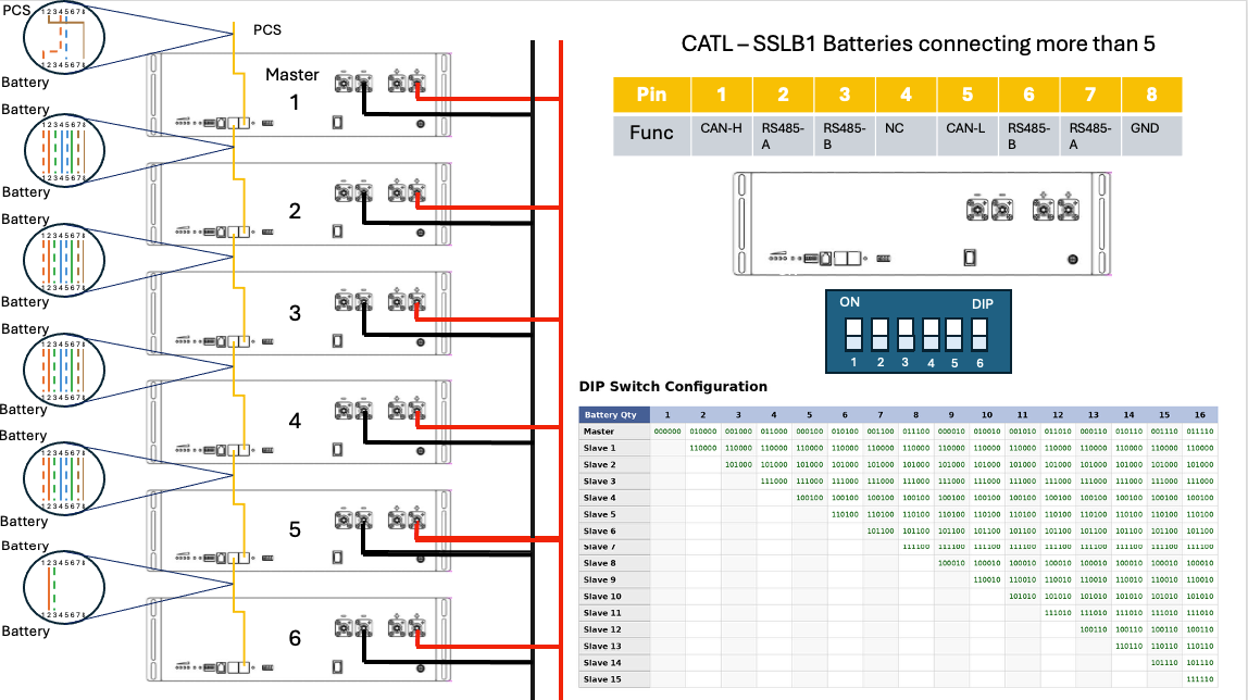
The inverter to master battery cable is a crossover cable, pin outs can be found in our knowledge base article SSLB1 - Battery Communication Cables
The battery to battery comms cables are straight patch through leads (no crossover of pins) connected to the ports marked CAN/RS485, however for the cable between battery 5 and battery 6 you must strip away the unused cores to prevent the interference.
The two pins which should remain connected by the two cores from a CAT 5 or CAT 6 cable are the RS485-A and RS485-B which uses pins 2 and 3 (2=A and 3=B) or pins 6 and 7 (6=B and 7=A) and the other cores must be terminated so that they are not making a connection to the RJ45 connector.
It is also recommended to have the parallel comms cables running IN to the right hand side CAN/RS485 port (closest to the green dry connector strip) and running OUT of the left hand side.
Image below to show this visually as well as the necessary dip switch configuration.
Was this article helpful?
That’s Great!
Thank you for your feedback
Sorry! We couldn't be helpful
Thank you for your feedback
Feedback sent
We appreciate your effort and will try to fix the article